The next-generation lithography machine, ASML's latest sharing
Recently, researchers from Carl Zeiss SMT and ASML published a technical paper. In the paper, the researchers investigated Hyper-NA EUV lithography with a numerical aperture of at least 0.75 as a path beyond the current 0.55-NA high numerical aperture system, covering optical architecture, resolution potential, mask 3D effects, polarization, and the requirements for extending the existing EUV ecosystem.
Translation of the original paper is as follows:
EUV scanners with a numerical aperture (NA) of 0.55 have recently been launched on the market and are currently moving towards high-volume production. Given the long product development cycle of EUV scanners, the question of what comes after the NA 0.55 scanner has already arisen.
We propose the concept of an EUV scanner with a numerical aperture of at least 0.75, referred to as a Hyper-NA scanner. Hyper NA should enable maximum reuse of existing lithography infrastructure, such as masks, light sources, and production equipment for manufacturing these scanners.
Hyper NA can support NA 0.75 within almost the same footprint as current NA 0.55 scanners. Existing light sources can be directly reused, and modern mask absorbers, such as low-n or high-k materials, are also sufficient for High NA. The increase in NA, and thus the introduction of Hyper NA, is a better alternative to current NA 0.55 scanners as it provides an infrastructure-compatible path forward.
Among the criteria considered in this paper — maintaining continuity with the current 13.5 nm EUV platform, reusing light source and mask infrastructure, compatibility with established scanner manufacturing techniques, and limited change in scanner footprint — Hyper-NA is the most straightforward extension of the current EUV scanner architecture.
Roadmap to Hyper NA
Figure 1 outlines all previous lithographic optical systems from Zeiss. With very few exceptions, all these optical systems follow the same curve in the resolution-versus-time plot. The slope of this curve has decreased since around 2010, reflecting the fact that the industry is taking longer to translate higher optical resolution into smaller pattern sizes in high-volume production. Conversely, the extended tool iteration cycles also reflect the greater investments required to develop these increasingly complex optical systems.
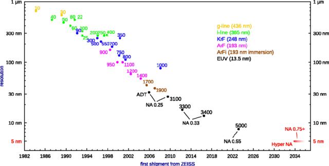
Figure 1: Evolution of Zeiss lithographic optics and their corresponding optical resolution
A simple extrapolation of this curve allows easy estimation of the performance of the next-generation tool: it should deliver an optical resolution of 5 nm half-pitch and be available around 10 years from now. This 5 nm resolution can be achieved by increasing the numerical aperture (NA) to a value of at least 0.75, hence the name "Hyper-NA".
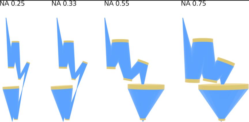
Figure 2: Projection lenses have different design classes, also known as folding geometries. Each folding geometry is only applicable to a specific range of numerical aperture (NA) values.
As the numerical aperture increases from 0.25 to 0.75, the lens size also increases. The transition from low NA (0.33) to high NA (0.55) required new production equipment to manufacture larger lenses, especially new metrology techniques to measure lens shapes during production. However, the impact of these changes was limited to the lens manufacturing process itself, with minimal impact on other aspects.
This is very different from the consequences of changing the folding geometry when moving from NA 0.33 to NA 0.55: different folding geometries lead to a substantial increase in system size, which affects tool users and their fab space requirements. Since the transition from NA 0.55 to NA 0.75 can be achieved with the same folding geometry, the system size will hardly increase, as shown in Figure 3, which allows the tool to be introduced into the fab almost seamlessly. In addition, it allows integration into future ASML high-throughput scanner platforms that are common to all numerical apertures starting from NA 0.33.
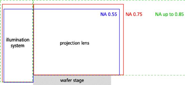
Figure 3: Comparison of optical path dimensions for Hyper-NA (NA 0.75) and its predecessor High NA (NA 0.55). Hyper-NA designs with NA values up to 0.85 are also available; however, the resulting increase in system size makes this option less attractive.
The numerical aperture is not limited to 0.75; on the contrary, we have designed optics with a numerical aperture as high as 0.85. However, the increase in NA significantly increases the system size, making this solution less attractive from the perspective of fab space and production costs.
Mask Infrastructure
Hyper-NA technology allows the reuse of most existing infrastructure. This is obvious for light sources, but it also applies to the underlying mask technology. To explain this, we refer to Figure 4, which depicts the angles at which different generations of EUV lithography masks operate. Low NA uses isotropic magnification, so the angular distribution (sine of the angle) is nearly circular. High NA and Hyper NA use anamorphic magnification, i.e. different magnification in the horizontal and vertical directions; as a result, the angular distribution is nearly elliptical with an aspect ratio of about 1:2.
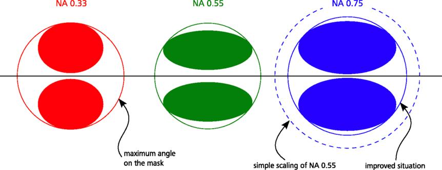
Figure 4: Comparison of EUV angular distributions at the mask, presented in angular space. EUV light comes from the illumination system (below the central horizontal line in the figure) and is then reflected by the mask to the projection lens (above the central horizontal line in the figure), which explains the mirrored structure in the figure.
The challenge is to limit the maximum angle on the mask. A simple scaling of the NA 0.55 case would increase the sine of the maximum angle by 36%. However, the High NA concept includes improvements in optical design and mechanical layout that can significantly reduce the maximum angle. The current baseline is to keep the magnification at its High NA value, i.e. 1/4 (for x) and 1/8 (for y), but by changing the magnification by a few percent, the maximum viewing angle can be further (albeit slightly) reduced.
All these improvements mean that the maximum angle encountered by NA 0.75 Hyper NA will only increase slightly, by ~1 degree compared to the High NA tool. This increase is very modest, and we expect that the current mask infrastructure can be reused with no or only minimal modifications, which is also confirmed by preliminary detailed simulations of mask effects.
Imaging Advantages of Hyper NA
The increased numerical aperture brought by Hyper-NA can be exploited in two different ways, which we will explain using Figure 5.
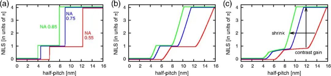
Figure 5: Comparison of imaging contrast at three different numerical aperture (NA) values. Figure (a) shows the ideal case without mask and vector effects, Figure (b) considers the effect of finite pupil fill, and Figure (c) additionally includes the effect of resist blur.
Figure 5(a) illustrates how increasing the numerical aperture (NA) changes the available imaging contrast under increasingly realistic assumptions: imaging contrast depends only on the diffraction orders that interfere at the wafer; therefore, for each NA value, the contrast curve exhibits a finite number of step changes. When a finite pupil fill is introduced [Figure 5(b)], these abrupt changes are smoothed out, but plateaus corresponding to discrete NILS values still appear. If resist blur is further considered [Figure 5(c)], these plateaus become slightly sloped, at least for small half-pitches. (Resist blur is modeled as a Gaussian convolution of the aerial image. The blur parameter used is 2.0 nm (1-sigma). Resist thickness effects, thin film absorption, standing wave effects, or 3D mask/resist effects are not included here.)
The two arrows in Figure 5(c) mark two different paths to leverage the benefits of increased NA: one option is to use it to shrink printed structures (with NILS kept constant); the other path is to use the increased NA to improve imaging contrast without reducing structure size, thereby increasing yield in high-volume production.
Vector Effects and the Need for Polarized Illumination
When discussing Hyper-NA technology, the topic of vector effects is frequently encountered: when there is a large angular separation between diffraction orders at the wafer (i.e. for tiny structures), only one of the two polarization directions can produce an aerial image with full contrast.
Without vector effects (and ignoring mask effects for the sake of discussion), with a fixed k1 value — i.e. with the numerical aperture appropriately adjusted for each pitch — the contrast of the aerial image would be independent of pitch (as shown by the red curve in Figure 6). However, when vector effects are included (which is the real-world scenario), the contrast varies with pitch even when k1 remains constant. For unpolarized illumination, this is represented by the green curve in the figure. Depending on the specific application scenario, polarized illumination can mitigate this contrast loss (see the blue curve in Figure 6).
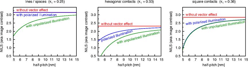
Figure 6: Vector effects reduce image contrast when unpolarized illumination is used. Depending on the specific application scenario, this loss can be mitigated by polarized illumination.
Figure 7(a) shows the two most extreme application scenarios: lines/spaces and square contacts. The corresponding illumination pupils are shown in Figure 7(b). For a single pole in the illumination pupil, the relevant diffraction orders are shown in Figure 7(c), with labels indicating which diffraction orders will interfere. For square contacts, at the k1 values used in EUVL, each illumination pole will image both the horizontal and vertical feature edges.
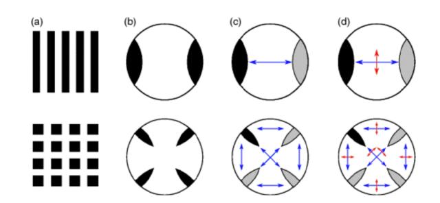
Figure 7: a) Corresponding structures, (b) corresponding illumination pupils, (c) for one illumination pole (black), other diffraction orders (gray) and which diffraction orders can interfere (blue), and (d) for each interference pair, the optimal polarization direction (red).
For a given pair of diffraction orders, the optimal polarization direction is orthogonal to the k-vector connecting the two orders, and this optimal polarization direction is shown in Figure 7(d). For lines and spaces, it is obvious how the two poles in the illumination pupil must be polarized to achieve this direction. Therefore, for this application scenario, the contrast loss caused by vector effects can be fully recovered.
For square contacts, Figure 7(d) shows that there are four different optimal polarization directions, corresponding to each pair of interfering diffraction orders. In other words, a given pole in the illumination pupil needs to have four different polarization states at the same time. For the simplest mask model, i.e. an unbiased pure-amplitude Kirchhoff mask, the contributions of these four polarization states are of equal intensity; therefore, there is no preferred polarization state, and no polarization selection can outperform unpolarized illumination, as shown in Figure 6. If a more complex mask model is used, the contributions of these four polarization states will no longer be equal; as a result, polarized illumination will offer a slight advantage⁵, but the magnitude of this advantage and even the optimal polarization state will depend on mask assumptions such as absorber type and bias.
For hexagonal contacts, the feature directions imaged by each pole of the illumination pupil differ by 60 degrees. Therefore, a reasonable compromise polarization direction can be found, which explains the partial recovery of the image in this application scenario when using polarized illumination.
Even in application scenarios where polarized illumination can improve contrast, the practical adoption of polarized illumination remains debatable, as polarized illumination is always accompanied by significant light loss. It is wise to choose the solution that minimizes Edge Placement Error (EPE).
Figure 8 shows the current EPE budget. One important contribution (the rightmost box) is unrelated to optical properties, e.g. it includes platform errors, and is irrelevant to the discussion in this paper. Another smaller contribution (the middle box) depends on image contrast, which is exactly what can be improved by polarized illumination.

Figure 8: Current Edge Placement Error budget for ASML EUV tools, where the width of each box is proportional to its contribution to Edge Placement Error.
However, the largest portion of EPE depends on dose and contrast, and this error can be clearly attributed to shot noise. For any application scenario, it is necessary to evaluate whether the degradation of EPE caused by light energy loss under polarized illumination will exceed the improvement of EPE brought by contrast enhancement. In the implementation discussed in the next section, using polarized illumination based on an unpolarized light source will lead to significant transmittance loss. Therefore, the benefit must be evaluated by weighing "contrast recovery from vector effects" against "EPE degradation from reduced photon count". However, even with a polarized light source, the choice of polarized illumination is not obvious: polarized light sources have advantages for dense line exposures, but this is not necessarily the case for the more important application scenario of freeform polarization for exposing complex structures. We will discuss these implementation-dependent factors in the next section.
Implementation of Polarized Illumination
Although many (and even most) application scenarios will use unpolarized illumination to avoid precious EUV light loss — so Hyper NA systems will also support unpolarized illumination with efficiency comparable to existing EUV scanners — we have also conceived schemes to implement polarized illumination in Hyper NA systems to meet specific needs. For example, only minor modifications to existing EUV illumination systems (i.e. adding linear polarizers) can achieve almost arbitrarily complex polarization distributions on the illumination pupil plane.
To this end, we will briefly review the layout of a conventional illumination system, see Figure 9(a). Light from the EUV source enters the illumination system via an intermediate focus to illuminate the field facets. Each field facet then directs the light to the corresponding pupil facets,